
Ever since 7th grade, there had been a myth floating around that my school would be moving locations and would construct a brand-new, sleek building to replace our aging location. While the prospects of a modern facility seemed tantalizing, most of my peers were convinced that we would never even see the building before we graduated.
Well, I think it's safe to say that they were somewhat wrong, as we are now studying in that new building. After hearing that the move was official and it would be completed before I left, I was ecstatic. Renders of the new building looked amazing. However, when they revealed the location, I was a bit let down, as I was used to the wonderful three block commute I enjoyed at the time. At over a mile away, walking would be slow and undesirable, especially during the winter. After walking the distance to the new location, I figured that I had to find a solution.
At around the same time, my curiosity in longboards began to grow considerably after riding my cousin's for the first time. The high speed, combined with the smoothness of the ride and the optimal form factor made a longboard the perfect transportation device. With the new school's distance from my house, I decided that a longboard would be the perfect tool to efficiently commute to school. After trying the route with my own longboard, a road bump in my plan revealed itself: longboarding among cars and trucks in the street is quite dangerous and nerve-wracking. The combination between a longboard's inherent instability, combined with its lack of brakes, made my potential ride to school a wild one. It was a nice idea on paper, but in reality, it was not practical.
However, all was not lost. After learning more about developments in "boosted board" technology and other electric vehicles, I was intrigued. Electric boards like the Boosted Board seemed more safe and predictable than a regular skateboard because of their motor(s). By having control over my speed, I could maneuver, brake, and keep up with the pace of traffic. I also would not have to kick, which was one of the things that made longboarding dangerous (by kicking, you are shifting your balance onto one foot for a small period of time, which means you can lose your balance faster and ultimately go headfirst into traffic...). I was also convinced that an electric skateboard would made the morning commute a little less arduous -- would I possibly look forward to my morning commute to school now?!
The only --small-- issue with a boosted board is the extremely high price. At nearly $2000, there was no way I could ever afford something like that -- that would be a lot of hours playing violin in Times Square! I decided to utilize the knowledge and skills I learned from designing and building UAV's and multirotors. I wanted to design and build my own electric longboard.
A longboard itself is quite simple: a deck, two trucks, and 4 wheels basically make up the entire machine. Since I was more interested in the electronic and mechanical part of the electric longboard, I did not spend costly time designing my own longboard deck. I decided to buy an Arbor longboard deck, due to its stiffness, durability, and high quality, and I also bought trucks along with it. I specifically choose large wheels with evenly space holes in them so I could properly mount a pulley to them and so I could easily go over bumps and small debris on the road.

Once I had the longboard, I started to design the electronics portion. I would need four main systems: remote control via a radio link system, a PWM motor controller that the receiver could communicate with, a drive system that would have enough torque and efficiency to enable me to move efficiently around the city, and a battery to power the machine. I started off with the drive system, as that would be the most complex.
The drive system consisted of a brushless outrunner, two gears, a pulley, a wheel, and a motor mounting system. When choosing the gears and the motor, I had to calculate a variety of factors which would help me with my choice. I first figured out the optimal speed I desired to go, and using the wheel size on the longboard, I converted from mph to rpm. I then figured out a gear ratio that would work with a low kv motor, as I wanted the motor to have greater torque and higher efficiency. Had I gone with a higher kv motor, the motor would be turning faster, and thus would waste more energy (higher kv also typically has a smaller stator size). A lower kv motor would also have more torque because the size of the stator would be larger and would be able to exert more rotational force (torque) over the gear that would be attached to it. I decided to go with a 190kv brushless outrunner that ran on a 6s Lipo battery. Per volt, my motor would turn 190 rpm, but with a 6s battery, the motor would spin at 1140 rpm. For my desired optimal speed of 25 mph, that means that I would need a 28/12 gear ratio so that my wheels would have the correct rpm with my motor to push the board 25 mph. However, this doesn't account for weight and drag while I'm on the board, so the top speed would probably be around 20 mph, which was more than enough. With the drive train parts figured out, I ordered them all.
I also needed an ESC, so after some research, I found a waterproof, 6s compatible, 150A ESC that would be able to handle the high current draw of my motor. It was imperative that the ESC had motor braking built in, so I could apply force to all of the magnets in my motor to slow myself down. I ordered the ESC as well.
And I also needed a radio, so I bought the smallest hand-held RC car radio I could find on Hobbyking. So that was also ordered.
And finally I needed a battery. I would only truly determine how many mAH I would need until I tested the longboard. I decided to go with a 5200mAH 6s.
Now that I had the motors and pulley's sorted out, I needed to create a way of mounting the motor to the longboard, and have the pulley system connect the wheel to the motor. To do this, I decided to use a 1/4in piece of aluminum, which would be welded onto the truck. I would then cut out mounting holes for the motor. Easy!
Well, not so easy. As I began to draw up the motor mount in Solidworks and started to add dimensions, I realized that finding the correct positioning of the motor so that the belt in the pulley system was constantly taut would be tricky. I decided to use some of knowledge of geometry I had previously learned in 9th grade. I had two circles, which were joined by two lines tangent to those circles like this:

Once I figured out the distance between the two circles defined by the length of my belt, I could finish designing the motor mount. Here is what it looked like:

I also decided to make the motor mounting holes slots so that the motor could be moved backwards and forwards for finer adjustment if my calculations were not perfect, and also to deal with the belt stretching over time and thus my eventual need to re-tighten it by moving the motor forward. I then painstakingly cut it out of aluminum and drilled the proper holes (which was also incredibly slow), and then had it welded to the rear truck!
At about this time the rest of the parts for the drive train arrived. The gears were aluminum, and the motor seemed high quality. Now that I had a way to mount the motor, I needed a way to mount the gears to the motor and wheel. I would mount the 28 tooth gear to the wheel by using the circular hole pattern on the wheel and screws, and would mount the 12 tooth gear. First step was to drill holes into the 28 tooth gear so that it could be attached to the wheel. This seemed easy in principle, but drilling through metal is an absolute terror. I found myself tearing my hair out trying to hold the gear in place properly, despite using a clamp, so that I could drill the holes accurately, both of which of course didn't happen and led to my gear looking like a torn-apart hunk of aluminum:

I then had to push the gear out so that it would clear the lip of the wheel, so I came up with this very elegant solution:

I mean it worked; it attached to the wheel fine, but it was off center, which made the gear wobble in an elliptical pattern. Ugh. I was hesitant to have my gear 3D printed, but after drawing it up in Solidworks and editing it so it would fit perfectly, it was too nice not to try. I uploaded the STL file to Shapeways and a few days later it arrived in all its perfection. It fit exactly how I had imagined. So, that was a success. Now I just had to see how durable it would be in the long run, especially after using it every single day to get to school and back. I then attached the 12 tooth gear to the motor by using a small screw to make contact between the gear and the motor shaft. With all gears in place, I was ready to mount the drive train and get it running for the first time. After a successful installation, I was ecstatic to test it, so I quickly found a battery lying around and threw the ESC and battery on the top of the deck. Here's a video of the first ride:
It worked! Now all I had to do was make a casing for the electronics and I would have a basic prototype done right?
No.
The next day, I decided to do further testing, and took it for a real spin. I didn't make it down to the end of the street before the 12 tooth gear popped off. I was somewhat confused -- the gear seemed to be attached very strongly to the motor. I decided to go back downstairs to my workshop and tighten it down again and add epoxy to it. A few days later I took it out again and it seemed to work great! Until it didn't, of course. The same issue occurred again. It was a dreadful feeling hearing the sound of the motor spin and looking down to see my gear not moving at all, but spinning free from the motor. I was at a loss. I still didn't love the idea of having so many 3D printed mechanical parts, so I wanted to find a way to keep the aluminum gear. I didn't give up yet though! I figured that since the gear kept on slipping, I should increase the friction between the gear and the motor shaft to better hold the gear in place. Since I had a spare 12 tooth gear, I used that one and drilled out the hole so it would be a bit too tight on the shaft. Then, using a hammer, I smashed the 12 tooth gear onto the shaft ever so slowly. The result was an incredibly tight fit that seemed too good to fail. I then tried this new configuration, and this time, there was actually nothing wrong. I rode it for miles without an issue for a few weeks, and was elated. Now I just needed a casing for the electronics, and I would have a working machine.
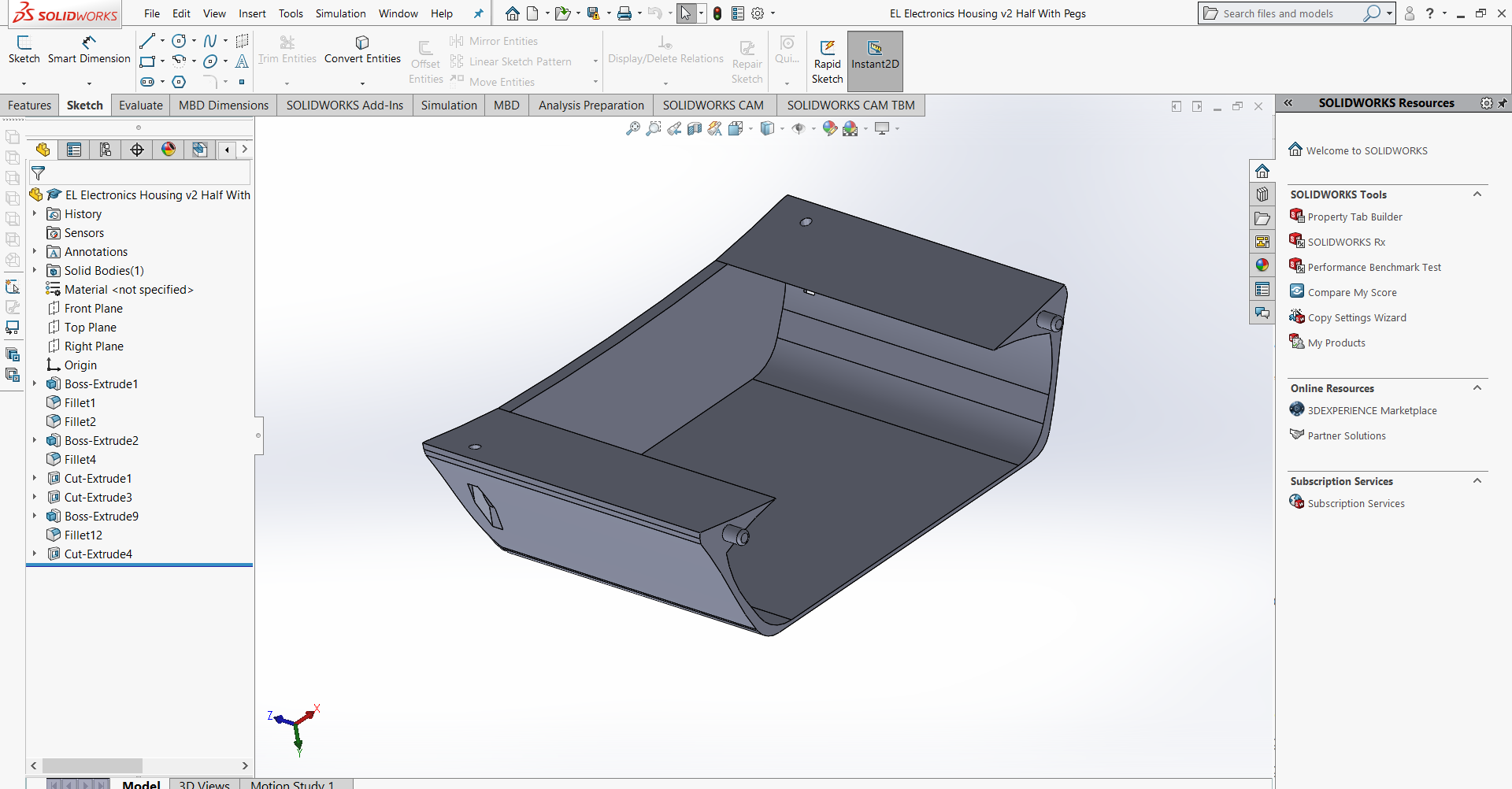
I wanted to 3D print the housing, so I drew it up in Solidworks (I print this two times and stick the two halves together):
And then sent it to Shapeways, only to see that the price to print such a large object was ridiculous, but justified. I decided to wait until school started to use their Lulzbot printer for free to print such a large case.
While I was waiting for school to start again, I rode my longboard around the city to test its range, practicality, and durability. For a couple weeks, it worked perfectly fine, carting me wherever I needed to go, until I tried to go to my violin lesson carrying a heavy violin case. As I hit the throttle to quickly accelerate, my beloved friction joint finally gave way, just as I had feared. I was troubled. Now that school was setting in, I would have less time to work on the board, and of course, it just had to break down. The following Friday I set out to try a new joint that used tape to tighten the fit between the motor shaft and the 12 tooth gear. Nope. Just as I rounded the corner to enter Central Park, the connection gave out. I headed back home in shame, pushing the board with my feet like some regular longboarder. My next attempt was to use the screw method again, but this time, I used epoxy to hold the screw in place and I filed a flat spot onto the motor shaft to increase the contact point and prevent the screw from slipping. Nope! The joint came loose at the exact same spot. I trudged home once again and tried my final idea: use Locktite. I smothered the screw hole and screw with the red substance (the unbreakable version of Locktite) and valiantly set out, hoping that I had found the solution. And the joint broke and the screw flew away at. the. exact. same. place. as. the. two. other. times. before. The combination of the little amount of threads in the screw hole with the high torque of the motor led me to ditch the idea. Instead, I finally turned to 3D printing for the 12 tooth gear, a decision I should have made a long time ago. This time, I gave the gear a flat part that would come into contact with a flat part on the shaft. Here was the new gear:

I ordered it from Shapeways, and while waiting for it, had my electronics housing printed. For some reason it became a school-wide phenomenon that someone was printing this giant thing that took 27 hours to print...
Now that I had the new 12 tooth gear and the housing, I could finish the first prototype of the longboard. I had to file down the shaft of the motor until I had a 1/4in wide flat spot on it to fit into the asymmetric shape of the gear hole. I then used a hammer to pound the gear onto the shaft. There was no possible way that the gear could slip -- for that to happen, the asymmetrical shape of the gear hole would have to be torn apart into a circle, which would take more force than my motor could possibly exert. The longboard was now complete -- all systems working consistantly.
I was proud that I had a working prototype just before we were going to move to the new school. I spent all of winter break riding it around outside the city, and discovered that the motor and electronics housing would occasionally be hit by bumps that were greater than or equal to an inch tall, so I had to be mindful of that while riding. It was a rare issue though that I would naturally avoid since a longboard cannot really go over large bumps in the first place. For nearly every bump, the clearance was perfect.
Here's a picture of the machine all finished:

Once we began at the new school, I quickly learned how valuable my machine was to my daily commute. Walking to the new location at a brisk pace took me nearly 22 minutes, which was unacceptable. With the longboard, it took me 7-8 minutes depending on the red lights. I was elated that my creation was actually so useful. It was a great feeling using something which I built and designed entirely on my own that was such an integral part of my day. I looked forward to riding it to school and back everyday.
However, I did learn some things. I now hate rain. Rain means I cannot take the longboard to school because I can't risk soaking the board. So I have to walk all the way there. Now rain tends to make my day much more annoying in general. Additionally, learning to make proper hand signals to other drivers indicating that I wanted to turn or change lanes was crucial to my safety, as I was essentially a car that could go faster than typical meandering traffic speeds.
After using it for nearly two months everyday, the board was showing no signs of slowing down. It was very dirty and weathered, but that only meant that I was using it and that I loved it. One day though, I had my first failure: a belt snapped. I quickly ordered a spare and set off again to ride to school. However, not a couple days later did I find that my weld, the one part of the board that I thought could not break, broke. I figured that the torque the motor had while trying to turn the wheel exerted a large amount of leverage over the motor mount, trying to pull it upward along a circular path. After enough hard accelerations, the weld must have cracked because of stress fracturing. I sent it to the welder's shop to have it fixed, and welded the mount in a better place to ensure that it does not fail again. The vehicle worked once again until the last week of school, when the 3d printed gears finally gave out and wore away so that the belt could no longer grip onto the gears. I was amazed that they lasted so long in the first place as I was using a prototyping plastic. Over the summer I will refurbish the board so it is fit for use during my junior year. This means printing more durable gears with the HP fusion material, waterproofing the housing, adding motor and drive train protection and a proper on-off switch, and making battery charging more convenient so that I don't have to remove the battery to charge it.
I also aim to add some automated features that can read and display battery life, speed and distance (once I have the time considering that I am also working on a VTOL project too!). At the moment however, I have designed a machine perfectly capable of fulfilling my needs for commuting daily to school and back. I think one of the great challenges this project presented, and still presents as I am still working on the board, is engineering a solution that is long lasting. It is difficult to make something that will withstand so many uses consistently and reliably, as seen in my dilemma with the gears. Look forward to more updates regarding the Arduino monitoring system!